
Selecting the Right Gear Shaper Cutter
A practical guide to specifying cutters for production and prototype gear work
Why cutter selection matters
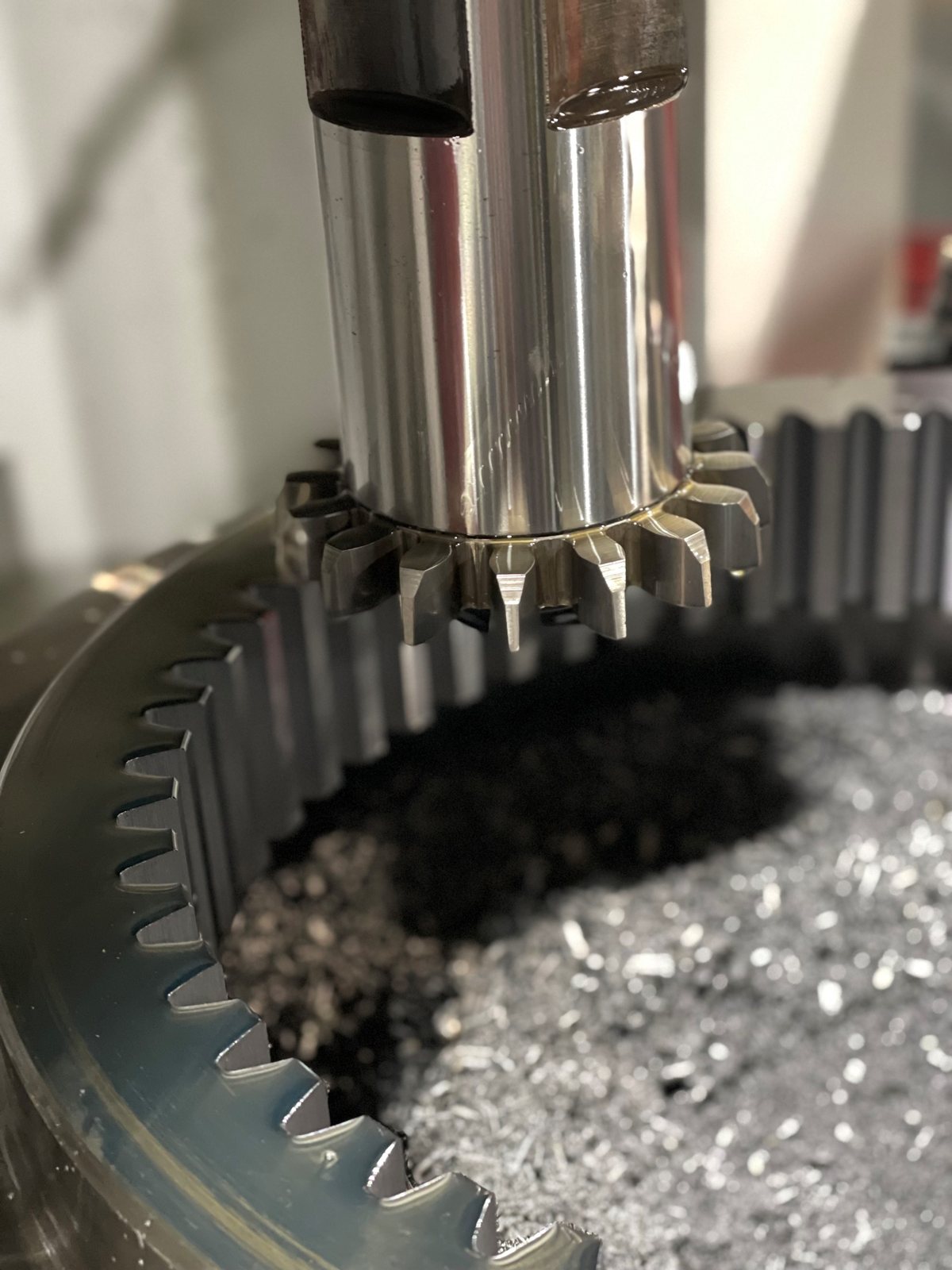
Gear shaping is one of the few generating processes that can produce internal gears, cluster gears, and gears that sit close to a shoulder or flange. The machine reciprocates a gear-shaped cutter against the blank while both rotate in time, generating each tooth flank stroke by stroke. Because the cutter is itself a gear, every detail of its design — module, pressure angle, helix, tooth count, geometry, and tolerance — is transferred directly into the work. A shaper cutter is not a generic tool that can be swapped out of a catalog drawer. It is engineered around the part it produces, and the wrong choice will show up as profile error, surface defects, premature wear, or scrap. This guide walks through the decisions that go into specifying a shaper cutter so the tool that arrives on the floor matches both the part print and the machine.
When shaping is the right process
Before selecting a cutter, confirm that shaping is genuinely the best fit. Hobbing is usually faster and more economical for external spur and helical gears with open access on both sides. Shaping wins when the part geometry blocks a hob: internal ring gears, cluster gears with a small gap between the teeth and a larger feature, shoulder gears with little overrun, sector gears, and certain face gears or non-involute forms. Shaping is also preferred when the gear has a stepped profile or interrupted tooth that a hob cannot reach. If the part can be hobbed without compromise, do that. If it cannot, shaping — and the cutter selection that follows — becomes the path.
Cutter types
Three families cover almost every shaping job, distinguished by how they mount and what kind of part they suit.
Disc-type cutters are the workhorse. They are flat, bore-mounted, and used for the bulk of external spur and helical gears. Disc cutters offer the most usable face for resharpening, which translates into the lowest cost per piece over the cutter's life.
Hub-type cutters are essentially disk cutters with an extended hub on one face. The hub provides clearance when a gear sits close to a shoulder, a flange, or another gear in a cluster. Specify a hub cutter whenever the print shows a tight shoulder run-out on either side of the teeth.
Shank-type cutters have an integral tapered or straight shank instead of a bore. They are mandatory for internal gears with small pitch diameters, where a bore-mounted cutter and its spindle nut will not fit inside the part. Shank cutters are also used on small external gears where a stiff, short tool overhang matters more than maximum cutter life.
A fourth variant, sometimes called a bell-type cutter, is a deeper hub design used for parts with extra-long shoulder clearance demands. Choose between the four by drawing the cutter into the part envelope and confirming clearance at the deepest stroke position.
Workpiece-driven specifications
A shaper cutter generates the gear by rolling with it, so its base specifications must exactly match the part. Module or diametral pitch, pressure angle, and tooth form standard (involute, stub, full-depth, AGMA, DIN, or proprietary) must be identical to the gear print. There is no tuning these in the machine; a 20° cutter cannot produce a 14.5° gear, and a module 2 cutter cannot make a module 2.25 gear. For helical work, the cutter is ground to a helix angle equal to the gear's helix angle, of opposite hand for external gears and the same hand for internal gears, and the machine carries a guide that imparts the rotational lead during the cutting stroke. Face width on the work sets the minimum useful face on the cutter, plus an allowance for overstroke and any chamfer or topping features. Internal gears further constrain the cutter: the cutter must have fewer teeth than the gear, and the cutter outside diameter must clear the gear root and any internal feature on the return stroke.
Cutter material
High-speed steel remains the most common substrate, and within HSS the grade is chosen for the work material and the duty cycle. M2 is the general-purpose default and handles mild steels and cast iron well. M35, with cobalt added, holds an edge longer in alloy steels and at higher cutting speeds. Powder-metallurgy HSS grades such as ASP 2030, ASP 2052, ASP 2060, S290 and S390 are finer-grained and more uniform than conventional HSS; they sharpen to a cleaner edge, resist chipping on interrupted cuts, and tolerate higher hardness in the workpiece — often into the low 40s HRC. Solid carbide shaper cutters exist but are limited to small modules on rigid CNC shapers because the impact loading of the reciprocating stroke is unforgiving to a brittle substrate. For the great majority of production work, PM-HSS is the strongest balance of edge life, regrindability, and toughness.
Coatings
Coatings extend tool life, allow higher cutting speeds, and reduce built-up edge on sticky materials. TiN is the long-standing baseline and is still appropriate for low-to-moderate-speed work in carbon steels. TiCN improves abrasion resistance and runs cooler in interrupted cuts. TiAlN forms an aluminum-oxide layer at temperature and is the standard choice for harder workpieces and higher speeds, particularly when coolant is reduced or eliminated. AlCrN (Alcrona) is favored for very high-temperature operations and where adhesive wear is the dominant failure mode; Altensa is designed for high-productivity cutting of case-hardening steels. Soft, gummy materials such as low-carbon free-machining steel or some non-ferrous alloys can actually run better uncoated, because the smoother sharpening surface releases chips more cleanly. Match the coating to the workpiece hardness, the cutting speed, and the coolant strategy rather than treating it as a free upgrade.
Number of teeth on the cutter
The cutter's tooth count is a real design choice, not a default. More teeth produce a more accurate involute on the work because the generating roll uses more, smaller increments — finish and form accuracy both improve. Fewer teeth give a smaller cutter outside diameter, which lets the cutter reach into smaller internal gears or tighter clusters. Cutter manufacturers publish recommended tooth-count ranges for each module and pressure angle; staying within those ranges keeps the generated profile within standard form-error limits. The interaction with the gear matters too: for internal gears, the cutter must have noticeably fewer teeth than the gear to avoid trochoidal interference at the tip. Confirm this geometry with the cutter supplier or with a generating-profile check before committing.
Special geometry features
Beyond the basic form, several optional features turn a generic cutter into a part-specific tool. Topping cutters cut the gear outside diameter at the same time as the teeth, which guarantees a concentric tip but consumes the cutter's tip corner faster. Semi-topping cutters add a small chamfer at the tip of the gear tooth in the same pass — useful for parts that would otherwise need a secondary deburring operation. Protuberance cutters undercut the gear root by a controlled amount so that a finishing operation such as shaving, grinding, or honing has clearance and does not have to remove material at the critical root fillet, where bending stress is highest. Chamfering cutters, sometimes stacked with the main cutter, knock down the leading edge of each tooth on the entry face. Each of these features must be specified up front; they cannot be added by the machine or recovered through regrinding.
Tolerance class
Shaper cutters are produced to recognized tolerance classes — AA, A and B in DIN 1829, with AGMA or ISO gear-quality equivalents available on request. Class AA is reserved for ground gears, master gears, and aerospace-grade work; the cutter itself is finish-ground to single-digit-micron tolerances on pitch, profile, and lead, and is priced accordingly. Class A covers most precision industrial production: automotive transmissions, machine-tool gearboxes, and quality-critical pumps. Class B is sufficient for general industrial gearing where the gear will be heat-treated and finished after shaping, or where loads and noise targets are modest. Specifying AA when A will do is a real cost penalty without a quality return; specifying B for a precision application invites scrap. Align the class with both the part print's quality grade and any downstream finishing process that will recover form errors.
Mounting and machine compatibility
A correct cutter still has to fit the spindle. For disk and hub cutters, the bore diameter, keyway position, and back-face hub diameter must match the cutter spindle and its driving features. For shank cutters, the taper (Morse or the machine builder's own) and the drawbar interface have to match. Maximum cutter outside diameter is bounded by the swing of the shaping head and the clearance to the work fixture at the return-stroke position. Stroke length on the machine must cover the gear face width plus approach, overrun, and any chamfer feature on the cutter. Before issuing a purchase order, line up the cutter drawing against the machine's spindle and travel limits, not just the part.
Sharpening, tool life, and cost per piece
A shaper cutter is sharpened on its top face — the rake face — and every sharpening reduces the cutter's axial length. Each grade and geometry has a published minimum length below which the cutter must be retired, even if the cutting edges still look usable. Plan the cost analysis around total parts produced over the cutter's sharpening life, not unit price. A PM-HSS cutter with a matched coating may cost two to three times a basic HSS-M2 cutter, but produce two to three times the parts between regrinds, with better surface finish at every stage. Establish a sharpening protocol with a qualified grinder: incorrect rake angle, burned edges, or uneven removal across the face will destroy a good cutter in a single regrind.
A selection checklist
Use the following sequence when specifying a shaper cutter. It runs from the part outward, so the cutter geometry, material, and class all derive from real constraints rather than habit.
| Factor | Decision driver |
|---|---|
| Cutter type | Disc for general external work; hub when shoulder clearance is tight; shank for small internals and clusters. |
| Material | M2 or M35 HSS for general production; PM-HSS (ASP 2030/2052/2060, S290, S390) for higher hardness or interrupted cuts; carbide only on rigid CNC machines. |
| Coating | TiN as a default; TiAlN or AlCrN for hardened, dry, or high-speed work; uncoated for very soft, gummy materials. |
| Pressure angle / module | Match the work exactly. Mismatches cannot be corrected by the machine. |
| Helix angle | Use a guide and a helical cutter: opposite hand for external gears, same hand for internal gears. |
| Number of teeth | Higher counts improve form accuracy and finish; lower counts give more usable life and reach into smaller internals. |
| Special forms | Specify topping, semi-topping, protuberance, or chamfer when the part needs root, tip, or finishing relief. |
| Tolerance class | AA for ground gears and master parts; A for precision production; B for general industrial work. |
| Mounting | Confirm bore, keyway, hub diameter, or shank taper against the spindle drawing before ordering. |
Closing
Gear shaping continues to hold its place in production because nothing else generates the same variety of internal, cluster, and close-shoulder gears with the same accuracy. The cutter is where most of that accuracy is born or lost. Treat each cutter specification as a small engineering problem: read the part print, confirm the process, choose the cutter type and tooth count against the gear envelope, match the substrate and coating to the work material, and pin down the tolerance class against the downstream finishing plan. Done deliberately, the result is a cutter that holds form across thousands of parts and many regrinds — and a process that earns its place against any alternative.
Estimate your shaping cycle time with our free shaping estimator, see the CTI gear shaper cutter range, or send us the print and we will specify the cutter.
Richard Potesta is the founder of CTI-USA, the North American sales, engineering and support partner of Capital Tool Industries and distributor for Eifco machines. Questions about an application? Contact CTI-USA or call 330-962-8160.
Need the tool this article describes?
Send us the print. We will specify the cutter or hob, recommend the tool steel and coating, and quote it.